Improvements to this document:
- Discuss Plugpoint Pattern in further detail, such as actual model and implementation. Could
point to lesson in BA Tutorial.
- Describe System Tree more - Point to BA Tutorial.
Introduction
A plugpoint is a predesigned point in a system for plugging in the desired behavior. A Plugpoint Framework
(PF) has one or more plugpoints plus built in system behavior.Without the supplied plugpoints the system will not
run. Once the plugpoints are supplied the system will exihibit behavior that is centered around the plugpoints.
A good example of a PF with a single plugpoint is Java Applets.
The Bean Assembler (BA) microkernel is a Plugpoint Framework. The Plugpoints
are the root marker class, the parex files, and the classes pointed to in
the parex files. Given all this, the microkernel does the rest to get the
system to run. Think of the BA as a super handy PF you don't have to write.
The BA is the PF on which you build all your other PFs. See Conceptual
Model of the BA.
Plugpoint Pattern
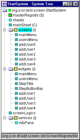
 To
the right we we see the Plugpoint Pattern used in a BA system. The "screens"
part is a container. It's children are "plug parts" such as mainMenu,
usersMenu, etc. The "screens" part implements the ScreenRegistry
interface, allowing it to play its role in the Modular Screen Subsystem
(MSS) Plugpoint Framework. If you dig into this framework, you'll see the
MasterRegistry contains 4 registeries, each of which contain plug parts. To
start the system the BA calls MasterRegistry.start().
The design of frameworks is the hard part, but you only have to do it once. The use of Plugpoint Frameworks
is the easy part, and we get to do that many times. This is the heart of why PFs are so powerful.
Plugpoint Framework design is just the "Plugpoint Pattern" using standard Object Oriented principles.
It's really nothing fancy. A PF's power comes from how adaptable it is to different customer needs, and how fast
you can create or modify systems. Add the fact that you never have to write your lowest layer PF, and you
have lots of power at your fingertips.
The Plugpoint Pattern can be thought of as a bunch of parts that make up a system. Some are already written
and do not have to be supplied. Others must be supplied by picking or creating "plug parts" and plugging
them into the parts that are supplied. Those parts that are supplied are the framework. Those parts plugged in
are what changes from system to system. The MSS System Tree shown is a typical Plugpoint Pattern example. Doesn't
it look simple?
System Tree Design
|
ModularScreenTest - System Tree
screenContext
screenRegistry
screenServiceRegistry
moduleRegistry
menu1, center
menu2, center
infoPane, bottom
viewRegistry
mainView (use configurable ViewStd)
--------------------------
screenContext.startScreen("Screen1")
|
Here's an example of a System Tree. This is taken directly from a Rational Rose model that had the Nutshell
Vision, Use Case List, Traits, Object Model and System Tree for the MSS. Dashes have been added to get an indented
look in html.
Usually you design the System Tree before the Object Model, especially if the system is similar to one you are
familiar with. Here's an early iteration of the System Tree for the MSS. Note how class names changed considerably
later.
The System Tree design is somewhat how you want the system _Container.parex file to look like. In fact on the
first implementation iterations we had all parts in the root _Container.parex file. Later the plug parts were put
into subdirectories. Notice how we even showed the promordial invocation. This was later changed to be called on
the MasterRegistry, which as you can see, was not even in the early System Tree.
After you've designed lots of BA systems, you will find that you're starting to sketch new system ideas on napkins
and scraps of paper in a quick hierarchy, just like the System Tree looks visually. This is a Good Thing, because
it means the physical and mental models are the same. This will eliminate the awkwardness we often see in systems
designed with one User Conceptual View and a completely different Physical View.
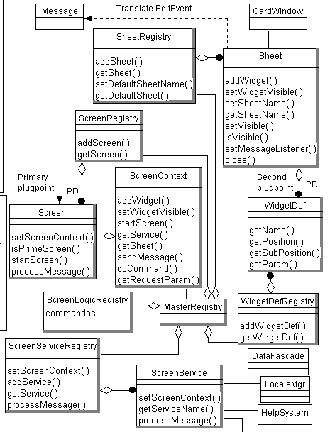
 Here's
the Object Model for the Modular Screen Subsystem. We have cropped a portion
of the actual model to get it to fit on this page. The objects with dark borders
are interfaces, allowing the framework to be very extensible.
For simple frameworks, no model is needed. The visual System Tree serves the purpose of the model. The MSS was
complex, requiring 9 days of analysis and design to achieve this model. The implementation was easy due to extensive
modeling.
Observe the MasterRegistry interface. This is the "brain" of the framework. It contains all other
registries. The implementation has a class implementing the MasterRegistry and ScreenContext interfaces. Thus the
"brain" serves both as the central switchboard and key context. This is what makes this framework so
simple to understand but powerful to use.
Most PFs need a model before implementation. When modeling, do a System Tree with text as soon as possible.
This will unite the model with the implementation and make future use of your PF much, much easier. Take a look
now at the MSS model and the System Tree. Can you see the relations?
The Screen interface is the main plugpoint and has 2 methods for the Standard Use Case discussed below. These
are startScreen() and processMessage(). The whole framework revolves around these two methods. All
other interfaces are designed to ultimately support these 2 methods.
PF Creation Steps
Read the definition of Plugpoint
Framework in Best Practices. The steps there are not oriented towards
a BA framework, so here's a list of steps that are. You can tune these to
suit yourself and your group. The rest is the Mini Process as usual.
- Start a Mini Process as usual. Get to the "Class models and other types of models" step.
- Define the "Standard Use Case(s)". This will help crystalize the framework structure.
- Design the System Tree you want to achieve. I usually do this first.
- Design the Object Model to achieve the tree.
In reality steps 2, 3, and 4 are so intertwined they may happen together. I'd estimate that about half the time
this is the case for my designs. The order can also vary. What we are doing here is breaking down a large monolithic
thing into parts.
Standard Use Cases
Here's a real trick. Don't tell anyone! :-)
The hardest part of design is moving from requirements to abstractions. Once you've done this a lot it becomes
easy, but even then tricks help. The abstractions are the objects, relationships, plugpoints, and dynamic behavior
response. The last can be a "Standard Use Case".
In the case of the Modular Screen Subsystem (MSS) the first step in design was to identify the "Standard
Use Case". This was not present in the requirements. Several days of thought and hen scratching led to seeing
that all we do when we let a user use screens is just 2 things: show the screen and then handle events.
Eventually an event leads to showing the next screen and the Use Case starts over. This abstraction was suprisingly
difficult to find. I did it by rewriting the Use Cases over and over, looking for groups, patterns, ways to simplify....
To help explain the above model, here's the MSS Standard Use Case:
1. Start a screen
- Put Widgets in Sheet
- Optional: Populate widgets with data
- Optional: Enable/disable controls
- Optional: Set focus on a control
- Optional: Save state from controls
2. Event received by a screen
- Optional: Validate data in controls
- Optional: Show invalid problem and stop
- Optional: Save data
- Sooner or later: Start next Screen with input data
This doesn't look at all like a normal Use Case, but that's what it is. We have just taken the Use Case mechanism
to a higher level of abstraction.
Helpful Hints
Run the MSS, study the model, study the code. This is a typical PF. The system marker class is org.jcon.test.screen.StartSystem.
Run it alone and in the BA Editor.
Do the same for the AutoTest system. The system marker class is org.jcon.test.screen.autotest.StartSystem.
Note how this system was designed to feed another system input by sending Messages. This is a simple example of
BA system collaboration.
Get bold and examine some larger systems using the Data Framework.
We have the CDC client and server systems. See the ReadMe file in gov/cdc/atsdr,
CDC ATSDR systems, available on the Downloads
page.
See the BA Tutorial for the rest of how to create
systems using the BA.
 To
the right we we see the Plugpoint Pattern used in a BA system. The "screens"
part is a container. It's children are "plug parts" such as mainMenu,
usersMenu, etc. The "screens" part implements the ScreenRegistry
interface, allowing it to play its role in the Modular Screen Subsystem
(MSS) Plugpoint Framework. If you dig into this framework, you'll see the
MasterRegistry contains 4 registeries, each of which contain plug parts. To
start the system the BA calls MasterRegistry.start().
 Here's
the Object Model for the Modular Screen Subsystem. We have cropped a portion
of the actual model to get it to fit on this page. The objects with dark borders
are interfaces, allowing the framework to be very extensible.